Core Technology

The technology behind wireless power through light

The energy chain
Electrical
Input
Laser
Source
Beam
Optics
Optical
Link
Receiver
Module
Regulated
Power Out

Optical power transmission converts electrical energy into a laser beam, sends that beam through free space, and converts it back into regulated electricity at the receiver. Each step in the chain, emission, propagation, and conversion, is governed by physical limits and engineering tradeoffs. Managing those limits is what makes the system deployable, safe, and credible in the field.

01 – Optical Power Control

Energy and Motion

Generating light is simple. Controlling it as a power carrier is the hard part. The transmitter must shape, collimate, modulate, and steer the beam while compensating for thermal drift, vibration, platform motion, and alignment error. Any loss at this stage affects the full energy chain.

High-efficiency diode or fiber laser matched to the receiver conversion band, selected to improve end-to-end efficiency before the beam leaves the aperture.

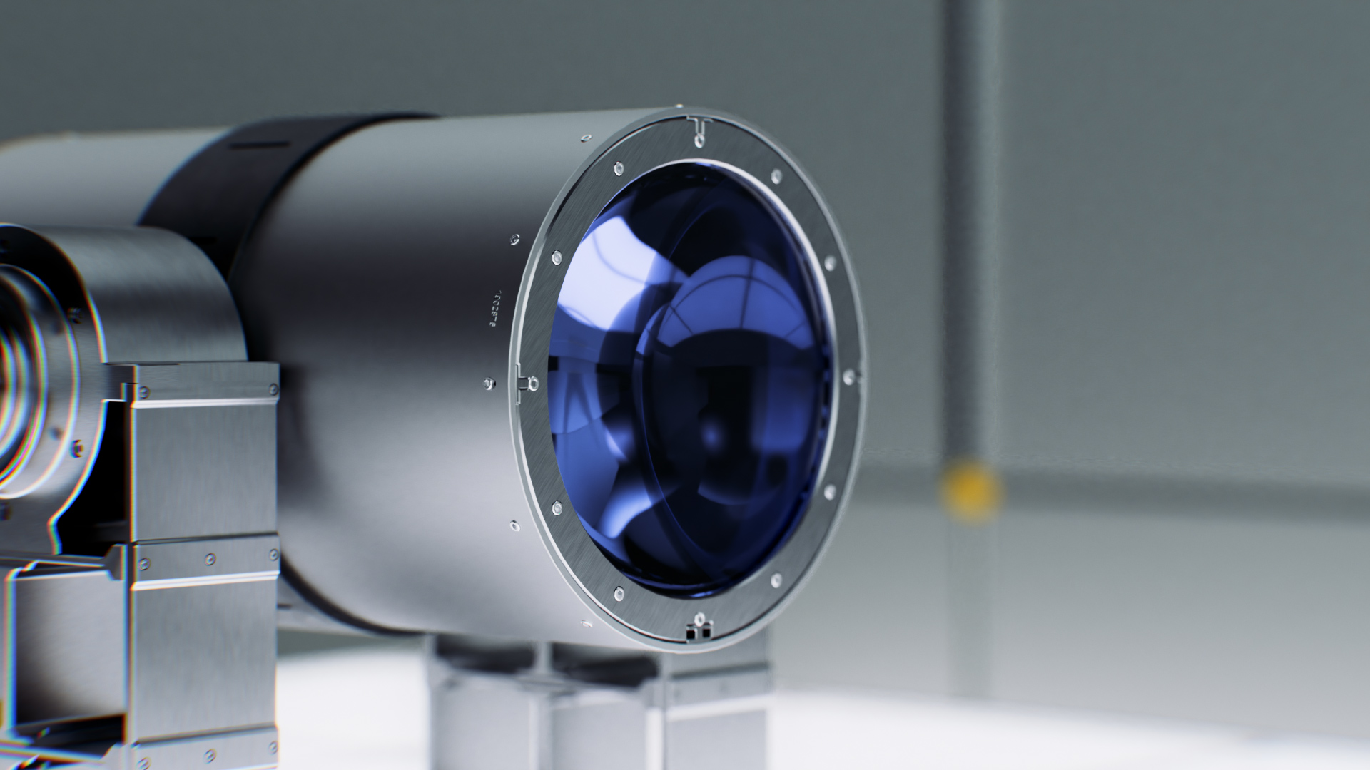
Optical elements control divergence, beam profile, and aperture use. Active alignment keeps the beam within operating tolerance across the target range.

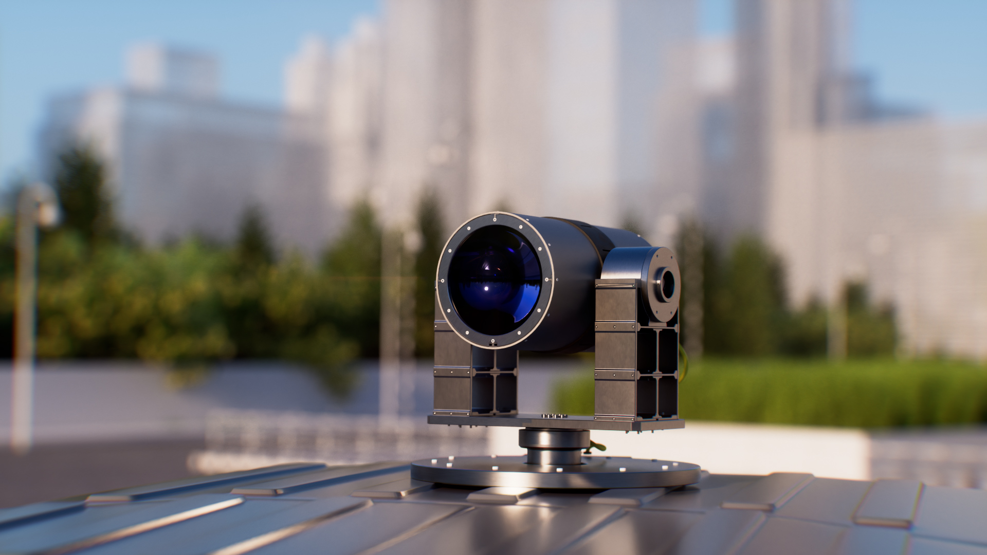
Closed-loop pointing compensates for platform motion, wind loading, thermal expansion, and receiver displacement. The transmitter continuously follows the target.

Emission is adjusted in real time using receiver feedback, link quality, environmental conditions, and safety state. Power is controlled, not simply switched on.

Transmitter health, beam diagnostics, pointing accuracy, and output power are monitored continuously. Deviations trigger adaptive correction or controlled shutdown.

System efficiency begins at the transmitter. A poorly controlled beam loses power before it reaches the receiver, and downstream electronics cannot recover it.

Optical transmitter beam shaping optics
02 – Wireless Energy Transmission

The optical link
replaces the cable

Energy travels as a controlled optical beam through free space. There is no conductive path and no physical infrastructure between transmitter and receiver. The link can connect fixed infrastructure, remote sensors, and mobile platforms where cabling is costly, slow, exposed, or impossible.

The link requires an unobstructed path between transmitter and receiver. Geometry, mounting height, and terrain clearance are primary design parameters.

Absorption, scattering, and turbulence depend on wavelength and weather. Fog, rain, dust, and thermal gradients affect availability and must be included in the link budget.

Beam divergence increases with distance. Receiver aperture size determines how much transmitted power is captured, especially at longer ranges.

The link does not radiate in the RF spectrum. It avoids interference with communications equipment, radar systems, and nearby electronics.

Ground-to-ground and ground-to-air configurations are both possible. Moving targets require active tracking, reacquisition logic, and clear operating envelopes.

The strongest use cases appear where cables, batteries, and solar panels each fail operationally. The optical link fills that gap without trenching or repeated battery maintenance.

Optical transmitter deployed on rooftop
03 – Receiver and Power Conversion

Engineered for the wavelength,
not the sun

A solar panel is designed for broadband sunlight. A laser power receiver is engineered around a specific wavelength, power density, and thermal operating point. It must capture the beam, convert it efficiently, regulate the output, and reject the heat generated during conversion.

Photovoltaic cells matched to the laser wavelength can achieve higher conversion efficiency than broadband solar cells under controlled optical input.

Receiver area, optical concentration, and beam uniformity determine how much incoming optical power becomes electrical output.

Power electronics convert the photovoltaic output into stable DC power for battery charging, direct device supply, or embedded power rails.

Conversion losses become heat inside the receiver. At higher power densities, thermal design sets the sustainable output level and protects lifetime.

Receiver modules must match aperture orientation, enclosure requirements, connector standards, and the mechanical interface of the host platform.

The receiver closes the energy chain. Its efficiency and thermal design determine whether optical input becomes useful power, or is limited by heat and load conditions.

Laser power receiver module
04 – Safety and Integration

Safety is part of
the control architecture

Laser power beaming requires controlled emission by design. Labels are not enough. Safety is implemented through monitoring, hardware interlocks, automatic shutdown, and certified operating modes. The system emits only when receiver validation, alignment confirmation, and operating-zone clearance are satisfied.

Laser classification, emission limits, and operating modes are developed around the IEC 60825 safety framework. Certification is part of product design, not a final checklist.

The optical path is monitored continuously. Interruption or foreign-object entry triggers automatic power reduction or shutdown without operator intervention.

Restricted operating zones are defined around the optical path. Physical and logical access controls support safe operation during transmission.

Receiver presence, power feedback, thermal state, and obstacle detection operate as independent monitoring channels to reduce single-point failure risk.

Hardware-level shutdown does not rely on software state. Physical cutoff mechanisms operate independently from the control interface.

Safe optical power is not a policy statement. It is a control architecture that prevents unsafe emission under defined operating conditions, with or without operator action.

Drone optical power link in field operation
Evaluate the Technology

Ready to assess optical power
for your application?

Share your use case, operating conditions, distance, and power requirements. We will assess whether a SunCubes configuration is technically viable for your deployment.

Or write directly to business@suncubes.space